ReluxCAD for AutoCAD –
Luminaire symbols
Learn how to use luminaire symbols in a consistent way for your different planning needs.
Aligning symbols to own usage
To align luminaire symbols to your own usage, click on internal symbol in the "Luminaire selection" > "Symbols" > "Allocate symbol" section.
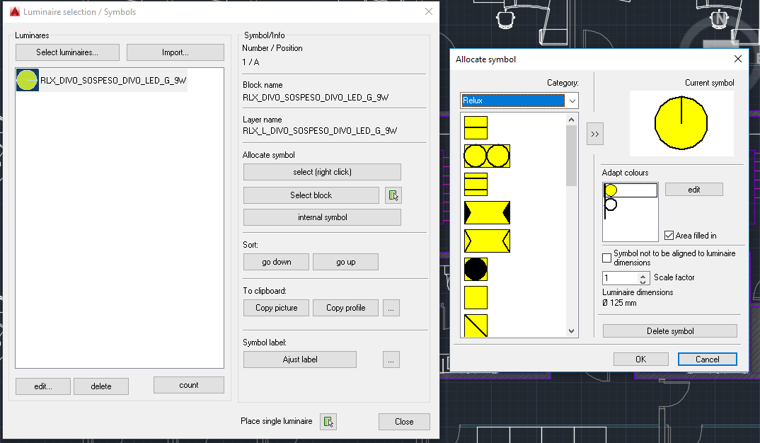
Luminaire selection (left) and own symbol usage allocation (ReluxCAD for AutoCAD).
Note: All standard symbols in ReluxCAD are shown to scale on the AutoCAD drawing. You cannot therefore influence the basic shape of the symbol for the luminaire you have selected. It is, however, possible for you to change the colour of the symbols in the Create symbol dialog window, to have them displayed in a particular colour or to have different patterns shown on the symbol.
Using your own symbols
ReluxCAD also supports symbols of external origin that are saved as an AutoCAD Block.
Click on the "Select" button (with the right mouse button) in the "Luminaire selection" > " Symbols dialog" window.
To align luminaire symbols to your own usage, click on internal symbol in the "Luminaire selection" > "Symbols" > "Allocate symbol" section.
Luminaire selection (left) and own symbol usage allocation (ReluxCAD for AutoCAD).
Note: All standard symbols in ReluxCAD are shown to scale on the AutoCAD drawing. You cannot therefore influence the basic shape of the symbol for the luminaire you have selected. It is, however, possible for you to change the colour of the symbols in the Create symbol dialog window, to have them displayed in a particular colour or to have different patterns shown on the symbol.
Using your own symbols
ReluxCAD also supports symbols of external origin that are saved as an AutoCAD Block.
Click on the "Select" button (with the right mouse button) in the "Luminaire selection" > " Symbols dialog" window.
Look in the window for the file that contains the symbol that has been drawn.
If you use symbols that you have drawn yourself, make sure that the symbol is drawn in a uniform layer, or ensure that all layers are in the same plane.
Symbols that you have drawn yourself are independent of the luminaire geometry. In other words, the scale of the symbol is not aligned automatically.
If, for example, you use strip lights with fluorescent lamps in different lengths, you should draw a separate symbol for each length.
Before you insert the symbol, you should make sure that the drawing is compiled to the same scale (units per meter) as the AutoCAD project into which the symbol is to be inserted.
Using existing symbols in the plan
If luminaire symbols are already drawn in on the plan, independently of Relux and ReluxCAD, you can allocate these to a Relux luminaire.
In this case, you no longer have to position any luminaires manually afterwards.
Please note, though, that after this operation in which the luminaire and the block are linked to each other, further operations, such as allocating a new symbol, can change the original block definition.
Take care only to link block/symbols with luminaires if these are intended for the purpose, and always save your original drawing.
Specifying style (reference block)
If you make frequent use of line or text styles, you can import these into your AutoCAD projects with ReluxCAD.
To do this, you must compile a reference block:
1. Open a new AutoCAD project
2. Draw any desired number of lines in the different styles that you wish to import.
If you also wish to import a text style :
1. Write a short text in the reference block and Allocate this the desired style.
2. Then select the corresponding file in the "Reference block" field of the "Project settings" dialog window
3. Click on the "Insert" button.
If you now wish to adapt your symbols, click on "Update all" symbol icon.
These same settings can also be made via the Setup command.
Labelling the symbols
A distinction is essentially drawn between different luminaires in ReluxCAD through the type of symbol employed.
If you want to label the luminaires on the plan, you can do this by drawing a symbol yourself and giving it the appropriate label.
Please note, however, that the labelling is firmly allocated to the symbol. If you rotate symbols, the text will be rotated too and will no longer be horizontal.
Overview of ReluxCAD for AutoCAD